A Question About Digital Radio
Why do the top three digital amateur radios not talk with each other?
I had a simple question, “Why can’t the three digital amateur radios talk with each other?” The simple answer is that there are three reasons: modulation, multiple access, and protocol. I was intrigued by the reasons and wanted to explore further. The focus of the discussion will be on modulation and multiple access.
Analog to Digital
A quick high-level review. Modern analog radios use frequency modulation (FM), which creates a constant bandwidth with a voice signal. An FM signal is a continuous “sinusoid” wave that has a smooth oscillation. When a user transmits, their voice signal is encoded within a carrier wave. As the voice is modulated it alters the frequency of the wave. The Radio Frequency (RF) is transmitted to another radio via an FM signal. The receiving radio demodulates the FM signal and creates an understandable sound wave or voice message.
Digital technology is entirely different from analog. Instead of encoding a voice signal onto a carrier wave, it is translated into binary format. This binary format is translated into a digital signal. Digital signals are not smooth continuous signals. They are exact and square in shape because it is transmitted via a non-continuous block segment. In the digital realm, it is either on or off.
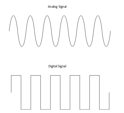
Figure 1 Digital vs Analog signals
Once the voice is converted to a digital signal within your radio, how is it transmitted? The easiest method is to use FM, which the radio is currently capable of doing. Transmitting digital data using an FM signal requires it to be modulated with digital information. Figure 2 shows the path used by a radio to convert speech to digital transmission by a radio.
The diagram shows the different stages during the conversion from speech to digital transmission. Each stage is numbered, orange box, and has a corresponding action listed below. Below each device is the waveform progress during the conversion.
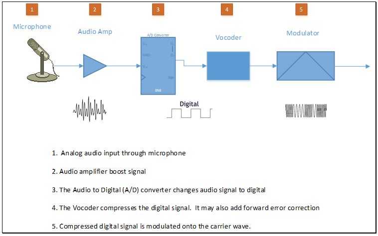
Figure 2 A representation of the conversion path of voice to digital modulation through a radio.
Modulation
Now that we have determined we will be using Frequency Modulation to send data, how is it accomplished? This is accomplished by using Frequency-shift keying (FSK). FSK is a frequency modulation scheme in which digital information is transmitted through discrete frequency changes of a carrier signal.
FSK was the first digital format that came into use. It communicates information by transmitting different frequencies. FSK can be thought of as being the same as analog FM which is modulated with a binary (two-level) signal that causes RF signal to switch between two frequencies. This basic understanding of FSK is required since we will be discussing other forms of this modulation used in amateur radio.
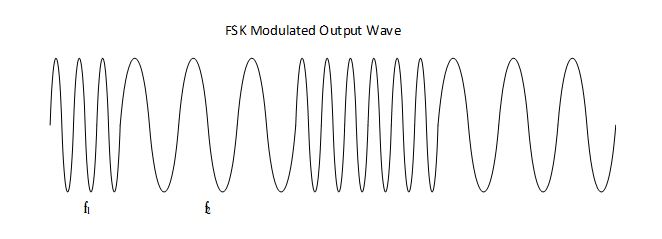
Figure 3 An example of FSK Modulation. In this example, F1 is representative of a binary 0 and f2 would be a binary 1. FSK is used to transmit binary code to another receiver, which is decoded and converted to sound.
The top three commercially available digital amateur radios use either Gaussian Minimal-Shift Keying (GMSK); Four Frequency-Shift Keying (4FSK); or Continuous 4-level Frequency Modulation (C4FM). We will review each of the modulation techniques. This will provide a better understanding of the key features of each and why they are not interoperable.
Gaussian Minimal-Shift Keying
To understand GMSK one must first understand Minimum Shift Keying (MSK). MSK is a particular implementation of FSK, which uses a baseband lowpass filter so that the transitions from one state to another (0 to 1) are smooth in time and limit the bandwidth of the modulated signal. MSK is known as a continuous phase scheme. Here there are no phase discontinuities because the frequency changes occur at the carrier zero crossing points. This arises because of the unique factor of MSK that the frequency difference between the logical one and logical zero states is always equal to half the data rate.
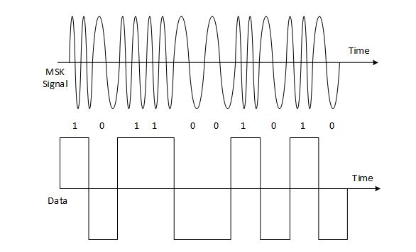
Figure 4 Concept of minimum shift keying, MSK signal. The top signal is an MSK signal and the bottom is a digital signal.
GMSK is a variant of MSK with waveform shaping coming from a Gaussian lowpass filter. It creates a narrow bandwidth and sharp cutoff frequency resulting in a more compact spectrum than MSK and enables better utilization of the available frequency spectrum. In an optimum GMSK system, 8000 bits/sec should pass through a 12.5kHz wide FM radio channel.
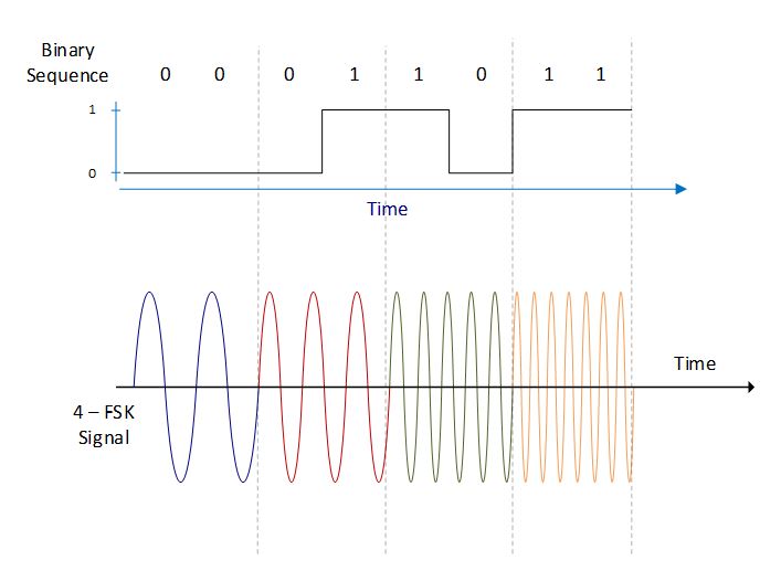
Figure 5 Representative of 1200 baud rate of an MSK signal. The top signal is an MSK signal and the bottom is a digital signal.
It turns out that GMSK has quite a bit in common with good old analog FM. Both modulation formats produce a constant amplitude signal, which makes them less susceptible to amplitude variations, including noise. GMSK is a popular modulation technique for wireless applications, including cell phone service, GSM.
Four Frequency-Shift Keying
4-FSK is a variation of FSK. 4-FSK is a frequency modulation that employs four frequency deviation levels, each of which communicates two bits of data. In other words, each frequency is representative of 2 bits of binary code. Each 2-bit code is assigned to a frequency shift of the carrier wave. As an example, the “01” code is assigned a +1050 Hz shift from the carrier wave, see table 1.
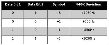
Table 1 4-FSK – bit, symbol, and deviation.
4-FSK does not have a set standard of frequency shift. The deviation can vary by manufacture or application. The one advantage of using this modulation over GMSK is the increased amount of data transferred.
Figure 5 4-FSK modulations, top) binary sequence, bottom) RF signal
Continuous 4-level Frequency Modulation
C4FM is similar to 4FSK, it has four different frequency deviations. Each frequency is representative of two bits of data (00, 01, 10, and 11) C4FM has a set standard of symbol frequency deviations (+/-600Hz and +/-1800Hz). C4FM contains no amplitude content, so simple transmitters similar to analog FM systems can be used. Table 2 shows each data bit for its frequency deviation. As displayed in table 2, it is obvious that 4-FSK and C4FM are the same except for the deviation values.
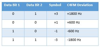
Table 2 C4FM bit, symbol, deviation.
Multiple Access
The next area of review is Multiple Access. When researching this subject, I often found the terms Multiple Access and multiplexing used interchangeably in some papers and websites, even though the terms do not have the same meaning. In Amateur, digital, radio Multiple Access is used. See figure 6 for the difference.
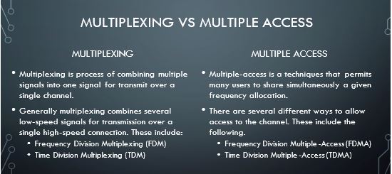
Figure 6 Multiplexing vs Multiple Access
Multiple access schemes are used to allow multiple data streams to share a finite amount of bandwidth. Amateur Radio uses different Division Multiple Access techniques, we will focus on two:
- Frequency Division Multiple Access (FDMA)
- Time Division Multiple Access (TDMA)
Frequency Division Multiple Access
FDMA is a channel access technique used in multiple-access protocols. Often referred to as a channelization protocol. As you may have guessed, the frequency band is divided into channels of equal bandwidth, Figure 7, so that each data stream is carried on a different frequency.
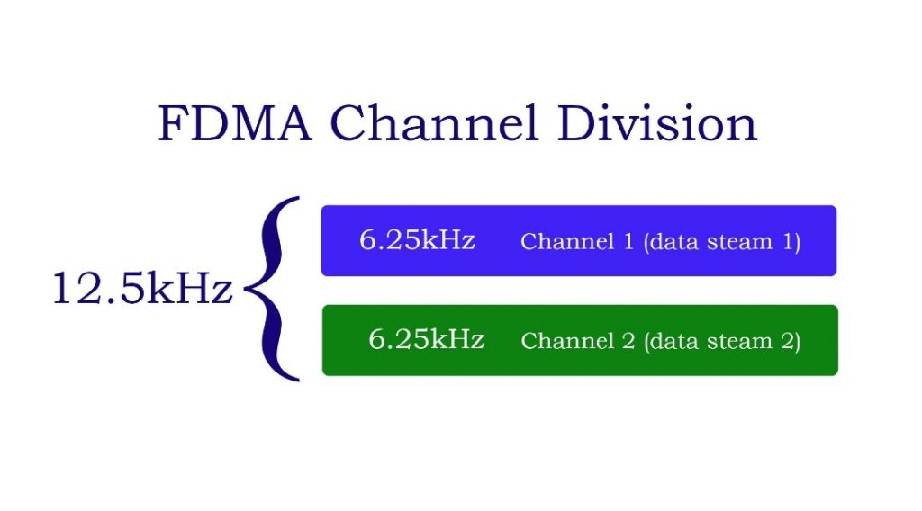
Figure 7 FDMA 12.5 kHz band divided into two 6.25kHz channels
FDMA divides the shared medium bandwidth into individual non-overlapping frequency sub-channels channels. Each sub-channel can be allocated to a separate data stream. This allows for transmission of voice, GPS location, and text messages (Call Sign) to be transmitted. In FDMA method, guard bands, Figure 8, are used between adjacent signal spectra to minimize crosstalk between the channels.
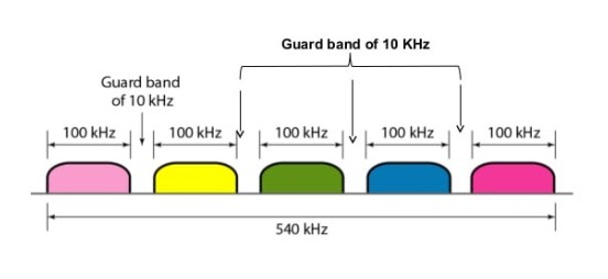
Figure 8 FDMA Guard Band (Vyas, 2014)
Time Division Multiple Access
TDMA shares a single carrier frequency with several data streams where each stream makes use of non-overlapping time slots. We will be looking at Two-Slot TDMA for our purposes. Data transmission in TDMA is not continuous but occurs in bursts. This is a complex technology because it requires an accurate synchronization between the transmitter and the receiver.
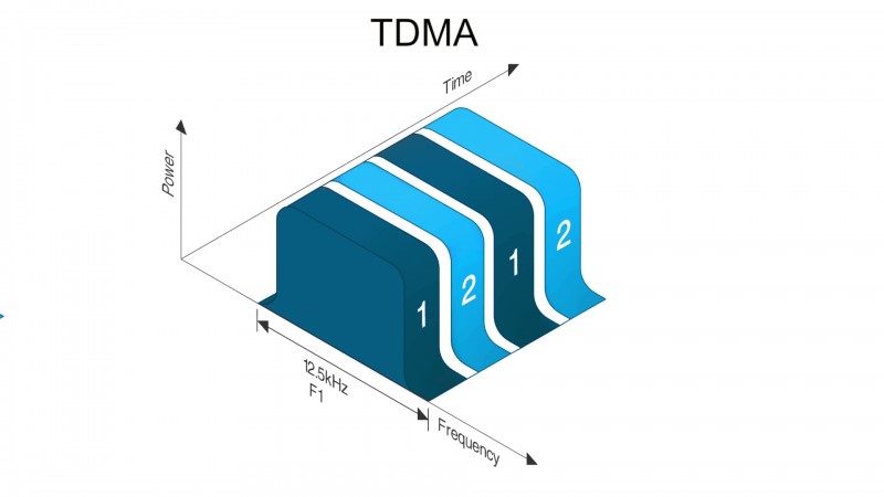
Figure 9 TDMA time slots (Farrelly)
A two-time slot TDMA system, two data streams can share the same frequency in the following manner: data stream 1 gets to use the frequency for a very short, fixed period of time, perhaps 50 milliseconds. Then, the channel reverts to data stream 2 for 50 milliseconds. It cycles again back to data stream 1 for 50 milliseconds. The cycle continues during transmission.
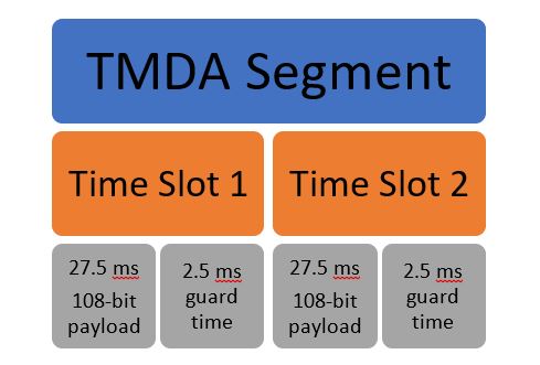
Figure 10 TDMA breakdown
Top Three Systems
Some say digital is the next frontier in ham radio. The spread of digital technologies has increased the options available for ham radio operators. Now that we have looked at the different modulation and multiple access techniques, we can see how they are employed in Amateur radio. The top three digital radio communication technologies we will review are D-Star, DMR, and Fusion.
Digital Smart Technologies for Amateur Radio (D-STAR)
The system was developed in the late 1990s by the Japan Amateur Radio League and uses Gaussian minimum-shift keying in its packet-based standard. It uses FDMA for multiple access techniques. D-STAR is an open-source protocol developed by ham operators. Currently, ICOM and Kenwood produce D-Star radios.
Digital Mobile Radio (DMR)
DMR is a limited open-source digital mobile radio standard defined by the European Telecommunications Standards Institute (ETSI). DMR uses 4FSK for RF modulation. It uses TDMA for multiple access. Commercial products around the world use DMR. There are several manufacturers of DMR radios.
There are two frequency bands, the uplink band, and the downlink band. In the uplink and downlink bands, each channel consists of 12.5 kHz bandwidth. Frequency is called a physical channel. Each channel is divided into two different time slots using TDMA technique. These slots are known as logical channels. TDMA there are two logical channels per physical channel.
Yaesu System Fusion (YSF)
Often referred to as Fusion, it’s the newest digital radio mode on the market. It was designed by Yaesu and is not an open standard. Yaesu is the only manufacturer of radios for this mode. It utilizes C4FM and FDMA for communications.
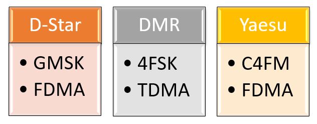
Figure 11 Digital Amateur Radio methods comparison
“Why can’t the three digital amateur radios talk with each other?” We have explored two of the three reasons that they are unable to communicate with each other. As shown in Figure 11, each uses different combinations of modulation or multiple access.
Below are a few links for additional information on each of the systems. The Yaesu site goes into more information about Fusion. DStar link has the A to Z about DStar, a great site for those starting out with DStar. Anyone interested in DMR radio, I found DMR for dummies site useful.
- Yaesu System Fusion – WHAT IS SYSTEM FUSION? | SystemFusion (yaesu.com)
- DStar – Home – D-STAR Info (dstarinfo.com)
- DMR – DMR For Dummies – All you need to know to get started using DMR in Amateur Radio
References
Farrelly, N. (n.d.). Introduction to DMR. Retrieved from Radio Academy: https://www.taitradioacademy.com/topic/what-is-dmr-1/
Vyas, S. (2014, Sep 28). Multiplexing & Multiplexing Hierarchy. Retrieved from SlideShare: https://www.slideshare.net/srashtivyas7/multiplexing-ppt15-sep
Scott Allison
KR3L