Early Radio Technology — The Marconi Coherer
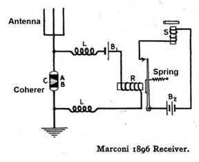
While reading about the early days of radio, I came across this schematic of a Guglielmo Marconi receiver, said to be similar to the one that copied his famous first transatlantic message on 12 Dec 1901.
Most hams will recognize the circuit components, with one exception – what is a Coherer?
Answer: The coherer was one of the earliest radio signal detectors and the first to be widely adopted. It played a critical role in the development of wireless communication.
In the early days of radio, the coherer was used to detect on/off modulated electromagnetic waves, which were known then as Hertzian waves. By 1896 Marconi was using a coherer to demonstrate short-range reception of Hertzian waves from spark-gap transmitters. Five years later a coherer detected his famous “dot-dot-dot” transatlantic message.
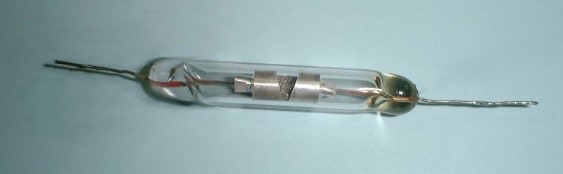
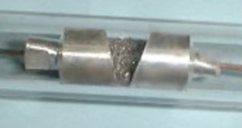
The coherer shown below is a modern remake of Marconi’s device. An evacuated glass tube encloses two silver electrodes separated by a small gap. The electrodes are connected to wires that extend through the ends of the sealed tube. The gap between the electrodes is loosely filled with metal filings. The facing surfaces of the electrodes are slanted, enabling the packing density of the material in the gap to be adjusted for optimal performance by rotating the tube about its longitudinal axis.
The coherer exploits an 1890 discovery by the French physicist Branly, who observed that a loose collection of sharply pointed metal filings in a glass tube increased its electrical conductivity when subjected to a Hertzian wave of sufficient intensity.
In the Marconi receiver circuit, antenna current induced by a passing Hertzian wave flows through the coherer to ground. If this current exceeds the coherer trigger threshold, the device “detects” the wave by switching to the high conductivity state. In the language of the day, the device switches from a state of non-coherence (low conductivity) to a state of coherence (high conductivity), thus the name “coherer”. Today this change in conductivity is attributed to micro-welding at the sharp points of the filings.
In its low conductivity state, the coherer will not pass enough current from battery B1 to pull in relay R. When the antenna current from a Hertzian wave flips the coherer to its high-conductivity state, the increase in B1 current through the coherer and the relay closes the relay contacts. In the sounder circuit, current from battery B2 flows through the closed contacts and activates the sounder S. The inductors L serve to isolate the coherer RF current path from the DC side of the circuit.
There is a complication. After detecting a Hertzian wave, the coherer remains in the high conductivity state indefinitely. To detect another wave the coherer must first be “reset” by tapping the tube, which returns the metal filings to their original non-coherent state. As early receiver technology matured, the manual reset was replaced by an electrically driven automatic tapper, greatly improving the speed at which successive waves could be detected.
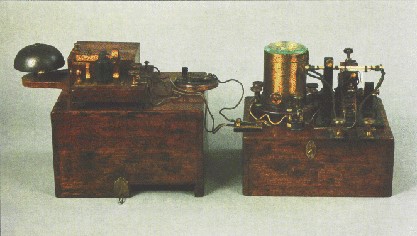
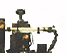
The coherer is drawn vertically in the schematic but was operated horizontally. The picture below shows an early Hertzian wave receiver with the horizontal coherer in the right foreground.
The coherer was mainstream radio technology until about 1910 when it was displaced by the crystal detector, which in turn was displaced by the vacuum tube detector in the 1920s.
For more details about the coherer, see Allen Mills, “The coherer: with simple demonstrations of the generation, propagation, and detection of radio waves”, downloadable at https://www.researchgate.net/figure/Coherer-Marconi-pattern_fig4_230901202.
Ted Fisher
K3SMT / AC8SW